 Inquiry

- Product Info
- SUMIKAEXCEL PES
- Welding
Welding of SUMIKAEXCEL PES
Since SUMIKAEXCEL PES is an amorphous resin, it is relatively easy to weld SUMIKAEXCEL PES to itself using a variety of methods. Table 5-2-1 shows the typical welding methods that can be used to weld SUMIKAEXCEL PES and their characteristics. Since the characteristics differ depending on the welding method, it is necessary to select a method taking into consideration the size and shape of the product, the characteristics required for the product, and economic efficiency (equipment price, cycle, etc.).
Table 5-2-1 Welding of SUMIKAEXCEL PES
| Welding Method | Hot plate welding | Ultrasonic Welding | Vibration Welding | Laser welding | IR welding | CVT (IR + vibration welding) | |
|---|---|---|---|---|---|---|---|
| Weldability | Welding Strength | ◎※ | ◎ | ◎※ | ◎ | ○ | ◎ |
| Appearance of the welded part | △ | ○ | ○ | ◎ | ◎ | ◎ | |
| Weldable resin | Thermoplastic | Thermoplastic | Thermoplastic | Light-transmitting resin Light absorbing resin |
Thermoplastic | Thermoplastic | |
| Welding Time | 10 to 30 seconds | 0.1 to 5 seconds | 2 to 10 seconds | 2 to 15 seconds | 10 to 30 seconds | 5 to 30 seconds | |
| Weldable size | Heater Size | Business card size | Pallet Size | Approximately A3 size | Instrument panel size | Instrument panel size | |
| Design | Product shape restrictions | Heater shape | fundamentally | Some degree of three-dimensional shape | High degree of freedom | Vibration welding | High degree of freedom |
| Welding Design | Exclusive Design | Exclusive Design | Exclusive Design | Exclusive Design | Exclusive Design | Exclusive Design | |
*Welding may not be possible due to the high softening temperature of PES.
Since SUMIKAEXCEL PES is an amorphous resin, it is relatively easy to ultrasonically weld SUMIKAEXCEL PES to itself. There are three possible welding combinations:
- Non-reinforced grades
- Unreinforced and fiber reinforced grades
- Fiber reinforced grades
Option 1 is the easiest and also provides the greatest welding strength. However, options 2 and 3 also provide sufficient welding strength, and are superior to crystalline resins (e.g. PPS).
The ultrasonic welding conditions vary depending on the horn output, product shape, welding area, grade, etc., but the standard conditions are as follows.
Table 5-3-1 Standard conditions for ultrasonic welding
| Pressure | 30~60 |
|---|---|
| Amplitude (μm) | 50~80 |
| Welding time (sec.) | 0.1~2.0 |
The measurement results of shear strength after ultrasonic welding are shown below. The test method and test pieces are as follows:
Ultrasonic Welder
SONOPET-1200B (Seidensha Electronics Co., Ltd.)
| Nominal output: | 1200W |
| Oscillation frequency: | 19.5kHz |
| Pressure: | 18N |
| amplitude: | 34μm |
Figure 5-3-1 Test piece for measuring the shear strength of welded joints
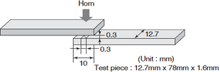
Table 5-3-2 Maximum load at the time of weld failure (tensile shear test)
(Unit: N)
| Oscillation time (sec.) | |||
|---|---|---|---|
| 0.1 | 0.2 | 0.3 | |
| 3600G | 680 | 700 | Breaking outside the welded area |
| 3601GL20 | 660 | 850 | Breaking outside the welded area |
| 3601GL30 | 740 | 830 | Breaking outside the welded area |
Laser welding is a method of welding by irradiating a laser beam and generating heat at the interface with the object. Laser resin welding combines a "light-transmitting resin (0.5 mm thick)" with a "light-absorbing resin (0.8 mm thick)." SUMIKAEXCEL PES has excellent light transmittance, making it possible to use laser welding.
Figure 5-4-1 Laser welding test conditions
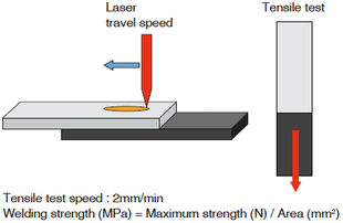
Table 5-4-1 Laser welding strength
| Grade | Laser conditions (Φ0.6) | Welding Strength (MPa) |
||
|---|---|---|---|---|
| Light-transmitting resin (Thickness 0.5mm) |
Light absorbing resin (Thickness 0.8mm) |
output (W) |
Movement Speed (mm/s) |
|
| 4100G | 4100GB | 3 | 10 | 30 |
| 15 | 33 | |||
| 20 | 34 | |||
| 3601GL20 | 3601GL20B | 3 | 10 | 38 |
| 15 | 37 | |||
| 20 | 37 | |||